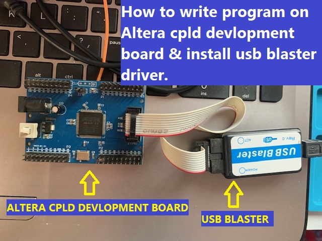
How To Write Blink Program On Altera Cpld Development Board And Install Usb Blaster Driver.
To write a blink program for an Altera CPLD (Complex Programmable Logic Device) development board, you’ll typically use a hardware description language (HDL) such as VHDL or Verilog. Here, I’ll provide a simple example using VHDL for a basic blinking LED program on an Altera CPLD development board. Please note that the specific details may vary depending on the CPLD model and the development environment you are using.
- Assuming you are using the Quartus Prime software for Altera devices, follow these steps:
- Create a new project:
- Open Quartus Prime and create a new project.
- Specify the project name, location, and any other necessary details.
- Add a new VHDL file:
- In the project hierarchy, right-click on the “Hierarchy” tab and select “New” > “VHDL File.”
- Give your file a name, for example, vhd.
- Write the VHDL code:
- Open the
blink_led.vhdfile and write the following simple code:
- Open the
					library IEEE;
use IEEE.STD_LOGIC_1164.ALL;
use IEEE.STD_LOGIC_ARITH.ALL;
use IEEE.STD_LOGIC_UNSIGNED.ALL;

entity blink_led is
Port ( LED : out STD_LOGIC;
CLK : in STD_LOGIC);
end blink_led;

architecture Behavioral of blink_led is
signal counter : INTEGER := 0;
signal clk_div : STD_LOGIC := ‘0’;
begin
process (CLK)
begin
if rising_edge(CLK) then
if counter = 50000000 then — Adjust the value based on your clock frequency
counter <= 0;
clk_div <= not clk_div;
else
counter <= counter + 1;
end if;
end if;
end process;

LED <= clk_div; — Connect the LED to the divided clock signal
end Behavioral;
This code generates a simple blinking LED by dividing the input clock frequency.
- Compile the project:
- Click on “Analysis & Synthesis” in the “Tasks” pane.
- If there are no syntax errors, proceed to the next step.
- Assign pins:
- Open the “Assignments” menu and select “Pin Planner.”
- Assign the appropriate pin for the LED output (LED PIN 77 CLOCK PIN 12).
6.Compile & program the CPLD:
- Click on “Assignments” > “Compile Design” to compile the project.
- After compilation, click on “Program/Configure” to load the bitstream onto the CPLD.
7.Test the program:
- Connect an LED to the assigned pin on the development board.
- Power on the board, and the LED should start blinking.
DOWNLOAD USB BLASTER DRIVER FROM THIS LINK : https://marutiitexperts.com/aleta-max-ii-epm240-cpld-development-board-uses-usb-blaster-driver/
You can also use verilog code:
					module delay_500ms(delay, CLOCK_50);
output reg delay;
input CLOCK_50;

reg [24:0] count;
reg on_off;

always @(posedge CLOCK_50)
begin
if (count == 25’d24_999_999)
begin
count <= 25’d0;

delay <= on_off ? 1 : 0;
on_off <= !on_off;
end
else
begin
count <= count + 1;
end
end
endmodule