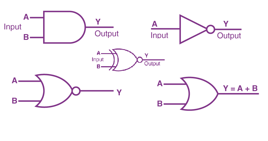
LOGIC GATES TYPES AND EXPLAIN WITH TRUTH TABLE
Logic gates are fundamental building blocks in digital circuits, responsible for performing logical operations based on binary inputs (0s and 1s). Each gate has a specific function and is defined by a truth table that outlines the output based on all possible combinations of input values.

1. AND GATE:
- Definition: The output is high (1) only when both inputs are high (1).
Truth Table:
| A | B | Output |
|---|---|---|
| 0 | 0 | 0 |
| 0 | 1 | 0 |
| 1 | 0 | 0 |
| 1 | 1 | 1 |
AND GATE EXAMPLE

- Function: The AND gate acts like a cooperative gatekeeper. It only allows a 1 output if both its inputs are 1. Imagine it as two switches; only when both switches are closed (ON) does the current flow, resulting in a 1 output.
2.OR GATE:
- Definition: The output is high (1) when at least one input is high (1).
Truth Table:
| A | B | Output |
|---|---|---|
| 0 | 0 | 0 |
| 0 | 1 | 1 |
| 1 | 0 | 1 |
| 1 | 1 | 1 |
OR GATE EXAMPLE

- Function: The OR gate is a more inclusive gate. It outputs a 1 if at least one of its inputs is 1. Think of it as a door; if either knob is turned, the door opens, and the output is 1.
3. NOT GATE:
- Definition: The output is the opposite (complement) of the input.
Truth Table:
| A | Output |
|---|---|
| 0 | 1 |
| 1 | 0 |
NOT GATE EXAMPLE

- Function: The NOT gate, aptly named, simply flips the input signal. A 0 becomes a 1, and vice versa. It’s like a mischievous switch that reverses the flow of logic.
4. NOR GATE:
- Definition: The output is low (0) only when both inputs are high (1).
Truth Table:
| A | B | Output |
|---|---|---|
| 0 | 0 | 1 |
| 0 | 1 | 0 |
| 1 | 0 | 0 |
| 1 | 1 | 0 |
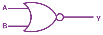
NOR GATE EXAMPLE

- Function: The NOR gate is the strict counterpart of the OR gate. It outputs a 1 only when both its inputs are 0. Think of it as a demanding rule: only when both conditions are not met does the output activate.
5. NAND GATE:
- Definition: The output is low (0) only when both inputs are high (1).
Truth Table:
| A | B | Output |
|---|---|---|
| 0 | 0 | 1 |
| 0 | 1 | 1 |
| 1 | 0 | 1 |
| 1 | 1 | 0 |
NAND GATE EXAMPLE

- Function: The NAND gate negates the AND functionality. It outputs a 1 only when at least one of its inputs is 0. Imagine it as a group vote; only when everyone disagrees does the output activate.
6. XOR GATE:
- Definition: The output is high (1) when the number of high inputs is odd.
Truth Table:
| A | B | Output |
|---|---|---|
| 0 | 0 | 0 |
| 0 | 1 | 1 |
| 1 | 0 | 1 |
| 1 | 1 | 0 |
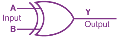
XOR GATE EXAMPLE

- Function: The XOR gate demands exclusivity. It outputs a 1 only when its inputs are different. Picture it as a jealous gate; it allows the output to flow only when one source is active, not both or neither.
7. XNOR GATE:
- Definition: The output is high (1) when the number of high inputs is even.
Truth Table:
| A | B | Output |
|---|---|---|
| 0 | 0 | 1 |
| 0 | 1 | 0 |
| 1 | 0 | 0 |
| 1 | 1 | 1 |
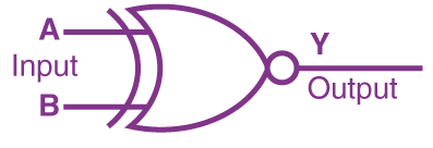
XNOR GATE EXAMPLE

- Function: The XNOR gate, the opposite of XOR, promotes solidarity. It outputs a 1 only when its inputs are the same. Think of it as a team player; when everyone is in sync, the output activates.
LOGIC GATES TYPES AND EXPLAIN WITH TRUTH TABLE
These logic gates are the foundation of digital circuits, and complex operations can be achieved by combining them in various ways. They are used extensively in computer systems, electronic devices, and other digital applications to perform tasks based on binary logic.


