Laptop Motherboard Communication Protocol And Uses
Laptop motherboards typically use various communication protocols to facilitate communication between different components and peripherals. Some common communication protocols found on laptop motherboards include:
1. PCI Express (PCIe): PCIe is a high-speed serial communication protocol used for connecting various internal components such as graphics cards, network adapters, and storage devices. It provides high bandwidth and low latency communication.
Signal Name : Transmit (TX) and Receive (RX) Data Lanes, Clock (CLK), [Control and Management Signals (Request (REQ), Acknowledge (ACK), Reset (RESET), Interrupt (INT), Presence Detect (PRES)], [Lane Configuration Signals, (LC0, LC1, LC2, etc.)], Reference Clock and Timing Signals, Error Detection and Correction Signals.

2. Serial Peripheral Interface (SPI): SPI is a synchronous serial communication protocol commonly used for communication between the motherboard and peripherals such as BIOS chips, sensors, and other embedded devices.
Signal Name : Master Out Slave In (MOSI), Master In Slave Out (MISO), Serial Clock (SCK), Chip Select (CS).

3. Inter-Integrated Circuit (I2C): I2C is a multi-master, multi-slave serial communication protocol used for connecting low-speed peripherals such as sensors, Battery, EEPROMs, and touchscreens to the motherboard.
Signal Name : Serial Data (SDA), Serial Clock (SCL).

4. Universal Serial Bus (USB): USB is a widely used serial communication protocol for connecting external devices such as mice, keyboards, storage devices, and smartphones to the laptop motherboard.
Signal Name : Data+ and Data-.

5. High Definition Multimedia Interface (HDMI): HDMI is a digital audio/video interface used for connecting external displays, TVs, and projectors to the laptop motherboard.
Signal Name : [TMDS Data Channels, TMDS Clock (CLK+ and CLK-), TMDS Data0 to Data2 (D0+ and D0-, D1+ and D1-, D2+ and D2-)], [TMDS Control Channels, TMDS Data3/4 to Data6/7 (D3+/D3-, D4+/D4-, D5+/D5-, D6+/D6-, D7+/D7-)], [Display Data Channel (DDC),DDC Clock (SCL), DDC Data (SDA)], Hot Plug Detect (HPD), Consumer Electronics Control (CEC), Audio Return Channel (ARC), Ethernet Channel (HEC).
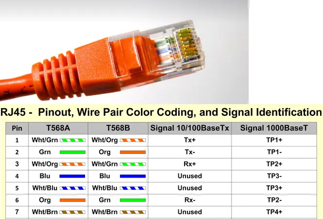
6. Ethernet: Ethernet is a networking protocol used for connecting laptops to wired local area networks (LANs) or the internet via Ethernet ports on the motherboard.
Signal Name : Tx+ and Tx- (Transmit Positive and Negative), Rx+ and Rx- (Receive Positive and Negative).
7. LPC (Low Pin Count) Bus: LPC is a low-speed parallel communication protocol used for connecting low-bandwidth peripherals to the motherboard. It typically involves a small number of pins for communication and control, hence the name “Low Pin Count.” LPC is often used for connecting essential system components such as the BIOS (Basic Input/Output System) ROM, embedded controllers, legacy I/O devices, and various sensors.
Signal Name : LFRAME# (Frame Signal), LAD[0:7] (Address/Data Bus), LADLE (Address/Data Latch Enable), LADWE# (Address/Data Write Enable), LADRE# (Address/Data Read Enable), LRDY# (Ready Signal), LCLK (Clock Signal), LRST# (Reset Signal), LDRQ# (DMA Request), LDRQACK# (DMA Request Acknowledge), LDEV# (Device Select), LFRAME# (Frame Signal).

Hard Disk Data Transfer Protocol
Certainly! Let’s explore the data transfer protocols used for hard disk drives (HDDs) and solid-state drives (SSDs) and the corresponding signal names on a computer motherboard:
- Serial ATA (SATA):
- Signal Names:
- Transmit Positive (Tx+): Carries positive differential voltage for transmitting data from the host to the device.
- Transmit Negative (Tx-): Carries negative differential voltage corresponding to the positive Tx+ signal.
- Receive Positive (Rx+): Carries positive differential voltage for receiving data from the device to the host.
- Receive Negative (Rx-): Carries negative differential voltage corresponding to the positive Rx+ signal.
- Clock (CLK): Provides the clock reference for data transmission between the host and the device.
- Description: SATA is the most common interface for connecting HDDs and SSDs to a computer motherboard. It uses differential signaling and supports higher data transfer rates compared to older parallel ATA (PATA) interfaces.
- Signal Names:
- Parallel ATA (PATA) / IDE:
- Signal Names:
- Data Lines (D0-D15): Parallel data lines for transmitting data between the host and the device.
- Address Lines (A0-A15): Parallel address lines for addressing memory locations on the device.
- Control Signals (e.g., RD, WR, CS): Signals for controlling data transfer operations, such as reading, writing, and chip select.
- Description: PATA, also known as IDE, was the standard interface for connecting HDDs and other storage devices before SATA became prevalent. It uses parallel communication and has been largely replaced by SATA due to its slower data transfer rates and wider cables.
- Signal Names:
- Serial Attached SCSI (SAS):
- Signal Names:
- SAS Data (SAS_TX, SAS_RX): Serial data lines for transmitting and receiving data between the host and the device.
- Clock (SAS_CLK): Provides the clock reference for data transmission.
- Description: SAS is a high-speed serial interface primarily used for connecting enterprise-grade HDDs and SSDs to servers and storage systems. It offers features like dual-porting and greater scalability compared to SATA.
- Signal Names:
- NVMe (Non-Volatile Memory Express):
- Signal Names:
- PCIe Data Lanes (TX+, TX-, RX+, RX-): Serial data lanes for transmitting and receiving data between the host and the NVMe device.
- PCIe Clock (CLK): Provides the clock reference for data transmission.
- Description: NVMe is a high-performance interface protocol designed specifically for SSDs connected via the PCIe (Peripheral Component Interconnect Express) bus. It offers significantly higher data transfer rates and lower latency compared to SATA and SAS.
- Signal Names:
These are the primary data transfer protocols used for connecting HDDs and SSDs to a computer motherboard, along with their corresponding signal names and descriptions. Each protocol has its own advantages, and the choice depends on factors like performance requirements, compatibility, and cost.
Type C Data Transfer Protocol
USB Type-C, commonly referred to as USB-C, is a versatile interface used in modern laptops and other electronic devices for various purposes, including data transfer, power delivery, and video output. USB-C connectors feature a symmetrical design, allowing for reversible plug orientation and compatibility with a wide range of devices. Here are the key signal names and their functions associated with USB Type-C in laptops:
USB Data and Power Delivery:
- USB 2.0 Data Lines (D+ and D-): Used for transmitting and receiving USB 2.0 data signals between the laptop and connected devices.
- USB 3.x Data Lines (Tx and Rx pairs): Used for transmitting and receiving USB 3.x SuperSpeed data signals, supporting higher data transfer rates compared to USB 2.0.
- CC (Configuration Channel): Used for determining the orientation of the USB-C connector and negotiating power delivery and alternate modes.
Power Delivery (PD):
- VBUS (Voltage Bus): Provides power supply voltage (up to 20V) from the power source (e.g., charger) to the laptop or other connected devices.
- VCONN (Voltage on CC): Provides power for active cables and accessories, such as USB-C to HDMI adapters or USB hubs.
- GND (Ground): Serves as the reference ground for power delivery.
Alternate Mode Signals:
- DP (DisplayPort): Used for transmitting DisplayPort video signals for connecting external displays or monitors.
- HDMI (High-Definition Multimedia Interface): Some USB-C ports support HDMI alternate mode for transmitting HDMI video signals.
- Thunderbolt: USB-C ports may support Thunderbolt alternate mode for high-speed data transfer and video output.
Audio Signals:
- Analog Audio: Some USB-C ports support analog audio output for connecting headphones or speakers.
- Digital Audio: USB-C ports may support digital audio output for connecting to external audio devices.
Miscellaneous Signals:
- ID (Identification): Used to identify the type of USB-C device and determine its function (e.g., host or peripheral).
- PD Control Signals (CC1 and CC2): Used for negotiating power delivery between the USB-C devices.
- SBU (Sideband Use): Used for implementing various functionalities, such as analog audio, debug interfaces, or additional data channels.
These are the primary signal names and functions associated with USB Type-C in laptops. USB-C offers a single, versatile connector for data transfer, power delivery, and video output, simplifying connectivity and enabling a wide range of features and functionalities in modern laptops and other devices.
UART Protocol
UART (Universal Asynchronous Receiver-Transmitter) is a popular serial communication protocol used for transmitting and receiving asynchronous serial data between two devices. It is commonly found in microcontrollers, embedded systems, and various electronic devices for communication with peripherals such as sensors, displays, GPS modules, and more. Here’s an explanation of UART signal and communication:
Signal Lines:
- TX (Transmit): The TX line is used by the transmitting device to send serial data to the receiving device.
- RX (Receive): The RX line is used by the receiving device to receive serial data from the transmitting device.
Data Transmission:
- UART communication is asynchronous, meaning that data is transmitted without the need for a shared clock signal between devices.
- Data transmission starts with a start bit, followed by a configurable number of data bits (typically 8 bits), optional parity bit (for error detection), and one or more stop bits.
- The start bit indicates the beginning of a data frame, and the stop bit(s) provide(s) a stable state at the end of the frame.
Baud Rate:
- Baud rate refers to the rate at which bits are transmitted per second (bits per second, bps) over the UART interface.
- Both the transmitting and receiving devices must be configured with the same baud rate for proper communication.
- Common baud rates include 9600, 19200, 115200 bps, and others, depending on the specific application requirements.
Flow Control:
- UART communication typically does not have built-in flow control mechanisms to manage data flow between devices.
- However, hardware flow control can be implemented using additional control lines such as RTS (Request to Send) and CTS (Clear to Send) for more robust communication in certain applications.
Synchronization:
- Since UART communication is asynchronous, the receiving device synchronizes with the transmitting device based on the start bit and baud rate.
- The receiving device samples the incoming data at regular intervals determined by the baud rate to reconstruct the transmitted data frames.
Error Detection:
- UART communication may incorporate error detection mechanisms such as parity checking to detect transmission errors.
- Parity bits can be configured as even, odd, or none, depending on the desired level of error detection.
In summary, UART communication involves the transmission and reception of asynchronous serial data between devices using dedicated transmit (TX) and receive (RX) lines. It is widely used for its simplicity, versatility, and compatibility with a wide range of electronic devices and applications. However, it does not provide advanced features such as flow control or error correction found in more complex protocols like USB or Ethernet.